


Quick guide for upgrade from X10 10.1" 2K color to X10 8.9" 4K mono
Kit includes:
A new ChiTu mainboard supporting 4K display:

A longer touchscreen cable.
A mounting bracket for the new but smaller LCD screen (8.9" 4K mono).
A new 8.9" 4K mono screen with its cable.

Key differences:
The main differences between standard 10.1" 2K color X10 and 8.9" 4K mono X10 are:
1, screen size is different.
2. screen orientation is different. 10.1" 2K's cable is on left side, while 8.9" 4K mono's cable is on top side. There are two changes due to this. One is that the new mainboard position will be different to old mainboard position, in order to accommodate the screen cable's natural shape. Another is the X, Y resolution in ChiTuBox slicer will be not only different on values, but also different on order.
Below is the new mainboard position:

Steps:
1, Take a few pictures of existing standard X10 layout and cables, including touchscreen cable connection. Also mark or remember the other cable connectors, i.e. which one goes to which slot. Main thing is the green plugs.
2, Remove old mainboard. Remember how those cables/wires were connected. You probably can label/mark each wire/cable you pulled off. Some connectors have some mechanisms to lock the cables. The touchscreen cable has two black little locks on each side of the connector. You can use finger nail to pop it loose towards cable direction. The LCD screen cable has a bar like lock on its top. You can use finger nail to pry it upwards.
Install new mainboard as shown in above picture. Note that the new mainboard mounting position is different to old mainboard. Remove old touch screen cable and install new and longer touchscreen cable. No need to reinsert screen cable on mainboard because you will install new one soon.
All cables/wires should be exactly reinstalled same as on old mainboard! You may use zip ties to do some cable management.
3, Remove existing LCD screen as you normally would do when you replace LCD screen. Typically, you first disconnect the LCD screen's cable on mainboard side. Then you start to peel off the black tape around old LCD screen,. Then you loose the 4 screws on mounting bracket of LCD screen. Then you can use a little screwdriver to access a little hole beside the LCD screen on one corner of its mounting bracket. This is to help lift up the old screen. Another safer way usually I do is to actually use the old black tape to help lift up. For that reason I usually only peel the black tape a little bit on each side off printer's body and keep majority of the tape intact on LCD screen and mounting bracket. Now you can lift up the screen and mounting bracket, along with screen's cable.
4, Install new mounting bracket with existing screws from old mounting bracket. Make sure the gap is installed on top edge. Tighten at least two screws right now!
5, Install the new cable on new screen. Do it gently as the connector pins are tiny. After connected, you may use some kapton tape or electric tape to help it secure on the LCD screen's PCB board, like below:

6, Now you can remove one side of the screen's protective film. The thin screen is glued to a thick glass. When you install the screen, the thick glass side is at bottom. DO NOT remove the top screen protective film if it is in ok shape and no bubbles. On the glass side, there is a thin plastic film we should remove, like below:

On top of the LCD screen, there is a little double sided red tape on one corner, which was meant to peel off the screen's protective film. But if the film is in good condition, you can just gently remove the red tape and keep the whole film. The red tape is just attached to the film.

7, Gently put the new screen into the mounting bracket on the printer. Make sure the cable is through the mount gap. If needed, you may use some old black tape again to help you lower down the screen into the bracket. If you have a helper, you can actually access the screen from back bottom window of the printer and the helper might be able to help you held the bottom of the screen from back access window, while lowering it down to the bracket.

8, At this point, please use some tape to temporarily secure the new screen to the mounting bracket. This is so that it won't fall off its mounting bracket, if you want to lay the printer on its back in order to access mainboard. You don't have to lay the printer on its back. You can install the screen cable from back bottom window. But it is up to you how you want to connect the cable to mainboard. To be cautious, it is best to temporarily use some old tape to secure the screen ti its mounting bracket.
9, The cable should be installed like below. There is a black plastic bar like lock to install the cable on mainboard side.

9, Check all connectors and make sure they are in their right places. Arrange cables and use zip tie if needed. Remove all tools to avoid short. Now you may plug in power and turn on the printer. The printer can still lay on its back if you want, as long as your LCD screen is temporarily secured. Do a display calibrate test in touchscreen menu. You should see something like below:

10, Now power off the printer. You are ready to secure all cables, screws.
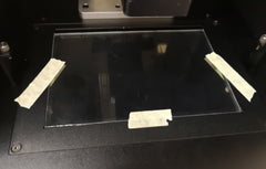
11, The last step is to apply black tape around the screen. The tape is to block the edge light of the LCD screen. At the same time, the tape can also protect the actual LCD screen. You can wear UV blocking glasses while applying tape around the screen, if you apply with light on. You can also apply the tape with no power. Below is the way to find out where the display edge is.


The tape needs to cover the edge of the actual LCD screen, not just bottom glass. The actual LCD screen is a very thin display glass on top of thick glass. Usually we cover 2mm of each side. As you can see in above pictures, the LCD screen glass is smaller than bottom thick glass. Make sure cover the edge of actual LCD screen so that when you slide in/out vat, you won't stress the edge of actual LCD screen. There is no pre-cut 8.9" inch tape yet but we will soon make some. For now you can use good electric tape, or just cut off from our 10.1" pre-cut tape.
11, You must relevel build plate each and every time you replace LCD screen. It is quite straightforward. Steps:
a, Remove vat, make sure build plate is clean and secured;
b, Loose the 4 screws holding the build plate;
c, Press home button, the build plate will sit on LCD screen;
d, Hold down the build plate with fingers, then tighten the 4 screws. You probably want to tighten them somewhat tight, then tighten them all secure in another round;
e, Press home and use a piece of paper to test the gap between build plate and LCD screen. Should feel some resistance;
f, Now press home again, then go back one level of menu on touch screen and select "Set Z 0" and confirm. That will set z starting position same as physical home position. In the future if you think that you want to make the gap a bit tighter to ensure bottom layers sticking to build plate, you may adjust Z 0 position by lowering it down 0.1mm only (from home position). Make sure 0.1mm only. This will make Z starting point 0.1mm lower than physical home position.
12, The new mainboard support CTB file format. You may create a new Generic profile in ChiTuBox and enter below values. After you sliced, please select CTB file format and save it. Otherwise if you still slice into CBDDLP file format, you will get below error message while printing:

Below are settings:


Further questions, please chat with us using our frontpage chat window, or email to support@epax3d.com.
Leave a comment